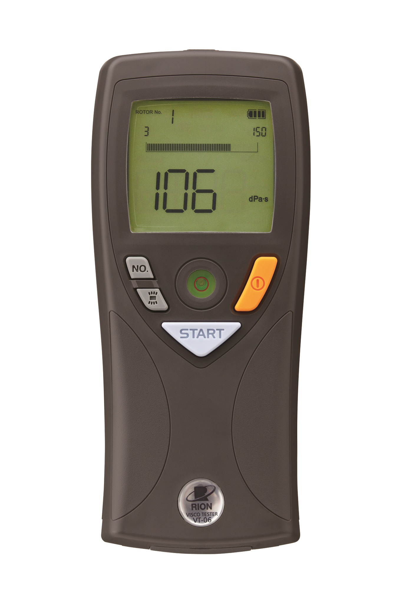
VT-06 | Viscometer
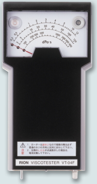 |
History of RION Viscotesters1957: First vibration viscometer V-1201 developed. 1960: Viscotester V-1207 developed and released to the market. 1965: VT-01 for normal viscosity and VT-02 for high viscosity released. Subsequent developments include the further improved models VT-03/VT-04 and VT-03F/04F. 2013: The Viscotester VT-06 with LCD panel is released. This model continues to be available today. |
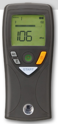 |
VT-06The VT-06 is designed for quality control applications in the manufacturing process of industrial products such as petrochemicals, paint, and adhesives, as well as foodstuffs. Viscosity measurements covering a wide range are possible, such as gear oil used in construction machinery. Measurement is performed by simply submerging a rotor in the fluid. The resistance to rotor movement caused by the viscosity (torque) is measured to obtain direct readings.
|
Specifications
details
| Applicable standards | CE marking, WEEE Directive, Chinese RoHS |
| Measurement range | (based on combination with the cup specified below “Sample fluid capacity”) |
| No. 3 rotor: | 0.3 dPa•s to 13 dPa•s (resolution: 0.1) |
| No. 1 rotor: | 3 dPa•s to 150 dPa•s (resolution: 1) |
| No. 2 rotor: | 100 dPa•s to 4000 dPa•s (resolution: 10) |
| Sample fluid capacity | |
| No. 1 and No. 2 rotor | Approx. 350 mL (with JIS 300 mL beaker) |
| No. 3 rotor | Approx. 150 mL (with No. 3 cup) Clearance between rotor end and cup bottom: about 15 mm |
| Measurement accuracy and reproducibility | ±10% ±1 digit of indicated value |
| Reproducibility | ±5% * Calibrated according to JIS Z 8809:2011 standard liquids for calibrating viscometer * The rounding error resulting from resolution occurs |
| Rotor speed | 62.5 rpm |
| Max. continuous measurement time per measurement | 100 s |
| Display value hold function | Value at end of measurement is retained |
| Backlight function | Switchable backlight Time until auto-off: 60 s (when rotor is not operating and unit is powered from batteries) |
| Auto shutdown function (when an AC adapter is not used) | If rotor is not turning and no controls are operated for 5 minutes, power is automatically shut off |
| Resume function | Last selected rotor number setting is retained during power-off |
| Ambient conditions for use | 5°C to 35°C, 10% to 90%RH (no condensation) |
| Power requirements | Alkaline batteries LR6, Ni-MH rechargeable batteries, or AC adapter VA-05J (5 V to 7 V : rated voltage 6 V) |
| Current consumption | approx. 250 mA (at maximum torque) |
| Battery voltage check | Displaying battery status (4 steps) |
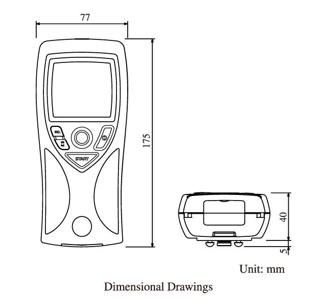
| Dimensions | 175 mm (H) × 77 mm (W) × 45 mm (D) (maximum) 175 mm (H) × 77 mm (W) × 40 mm (D) (without protruding parts) |
| Weight | Approx. 260 g (without batteries) |
| Supplied accessories | |
| No. 1 rotor (dia. 24 mm × 53 mm × 166 mm) | SUS304 1 |
| No. 2 rotor (dia. 15 mm × 1 mm × 113 mm) | SUS304 1 |
| No. 3 rotor (dia. 45 mm × 47 mm × 160 mm) | SUS304 1 |
| No. 3 Cup (dia. 52.6 mm × 75 mm) | SUS304 1 |
| Rotor extension (in a tube) (900 mm; 300 mm × 3) | SUS304 1 |
| IEC LR6 (size AA) battery | 4 |
| Instruction manual | 1 |
| Viscosity measurement guide | 1 |
| Inspection certificate | 1 |
| Optional accessory | |
| AC adapter | VA-05J |
| Stand | VA-04 |
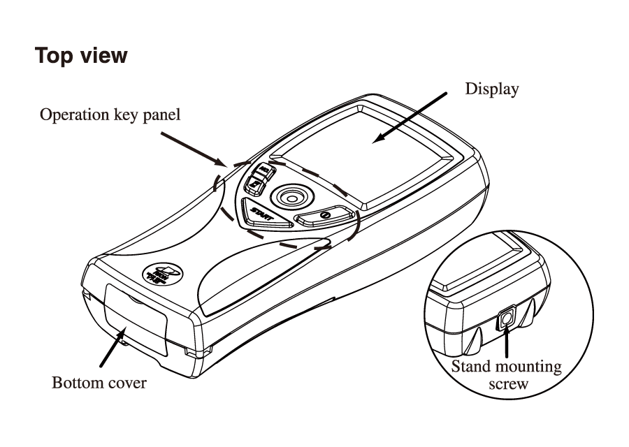
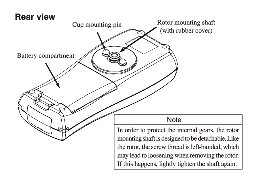
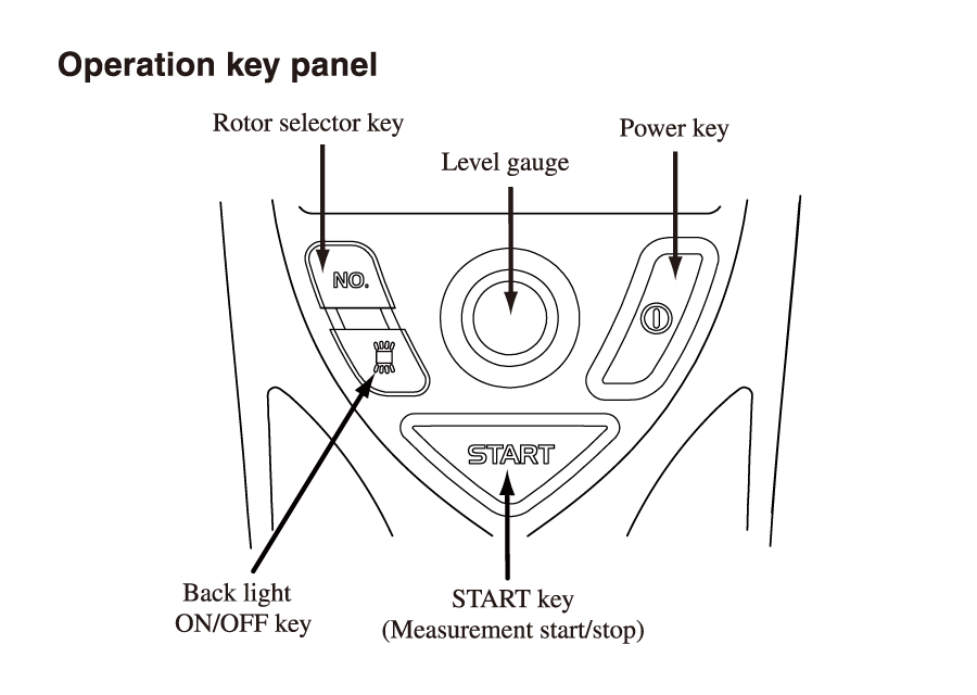
Controls and Functions
details
Technical Documents
details
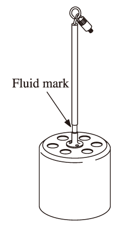
| Rotor extension The supplied foldable rotor extension consists of three 30 cm rods joined by rings. The combined length is 90 cm. When wishing to use the extension at a length of 30 cm or 60 cm, open the connector rings with a pair of pliers, remove the desired number of elements, and rejoin the extension rods. Be sure to close the rings fully again, to prevent the extension from getting detached during use. Attach the end with the male thread to the viscotester and the end with the female thread to the rotor. Note that both are left-hand (reverse) screw threads, so you must turn the parts counterclockwise to screw them in. When measuring a fluid with high viscosity, the joint will look as shown in the illustration, but this does not affect the measurement. The rotor extension rods are made of stainless steel. |
 |
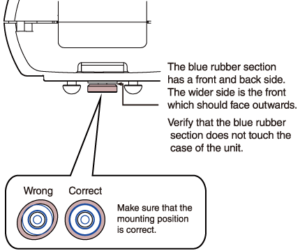 |
Attaching the Rotor
|
How to measure
details
|
 |
* About power swing
When the rotor starts to turn, temporary overload may cause a socalled power swing condition where the rotor cannot turn properly. In such a case, the indication “FAIL” is shown on the display, the rotor is stopped, and then started up again.
